
Bilkent University · 2026
ToolMind:
VLM-Guided Spatial Reasoning for Robotic Tool Use
Department of Electrical and Electronics Engineering, Bilkent University
Department of Electrical and Electronics Engineering, Bilkent University
Full ToolMind overview demo across all three constrained manipulation scenarios: wall retrieval, screwdriver insertion, and shelf retrieval.
ToolMind is a dual-modality pipeline for scenario-specific sequential robotic tool use. Given RGB-D observations of a tabletop scene, the system identifies the correct tool, predicts task-relevant grasp, functional contact, and waypoint keypoints, and executes a multi-phase manipulation sequence. GPT-5.5 handles semantic scene understanding, tool selection, structured keypoint reasoning, and waypoint generation, while a depth-based geometric module refines coarse VLM outputs into precise 3D keypoints.
The central challenge is spatial myopia: VLMs often regress keypoints toward object centroids instead of the task-relevant extremities needed for tool use. We mitigate this with a Structured Chain-of-Thought JSON prompting strategy that forces geometry → grasp anchor → contact tip reasoning before coordinate regression. The resulting keypoints drive KOMO-based trajectory optimization in a simulated Franka Emika Panda environment across wall retrieval, screwdriver insertion, and shelf retrieval tasks.
The pipeline requires no task-specific VLM retraining and operates in an open-world style: DBSCAN-derived cluster labels and per-cluster geometry summaries anchor the model's attention, while depth back-projection, point-cloud snapping, PCA geometry, and antipodal search convert VLM predictions into physically feasible robot actions.
DBSCAN clusters are projected back to RGB views as labelled regions, turning open image regression into a structured selection-and-localization problem.
The prompt requires explicit geometry, grasp-anchor, and contact-tip reasoning before GPT-5.5 is allowed to output coordinates.
VLM pixels are lifted through the registered depth channel, snapped to the selected tool point cloud, and refined with PCA and antipodal search.
The refined keypoints guide grasping, positioning, and execution phases for pull, insert/rotate, and sweep/push manipulation.
Four tightly-coupled stages connect raw RGB-D perception to physics-based trajectory execution. GPT-5.5 acts as the semantic backbone — selecting tools, predicting keypoints, and generating motion planning waypoints.
RGB-D capture from top-down + oblique views. Depth back-projected to 3D. DBSCAN clustering, alphabetic object labeling.
GPT-5.5 receives annotated RGB + cluster summaries. Outputs tool label, grasp region, contact pixel, and motion planning waypoints via CoT prompting.
Contact pixel back-projected to 3D via depth channel. PCA axis estimation, antipodal grasp search, vector-based tool orientation.
Multi-phase trajectory optimization: grasp → position → execute. Collision avoidance + joint-limit constraints on Franka Panda.
The original stage summary stays above. Below, you can directly show four example figures: DBSCAN + point cloud, clusters, VLM output for grasp, and VLM waypoint generation.
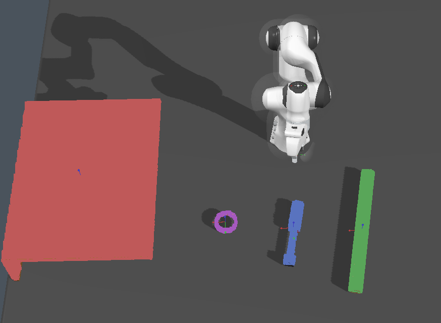
Back-projected scene point cloud before semantic reasoning.
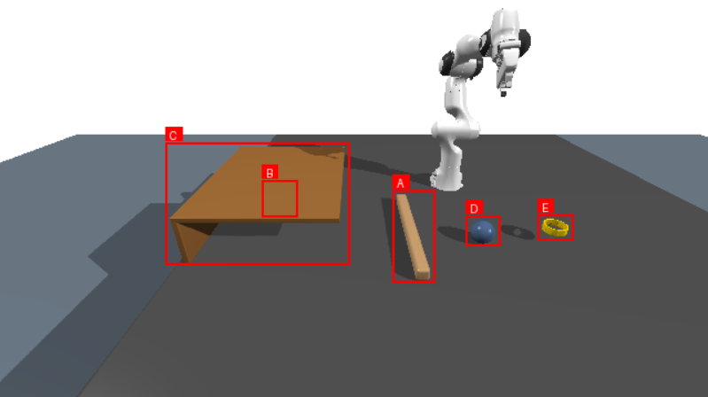
DBSCAN clusters and alphabetic object labels prepared for the VLM.
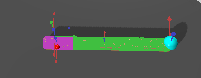
Annotated VLM prediction for tool selection, grasp region, and functional contact pixel.
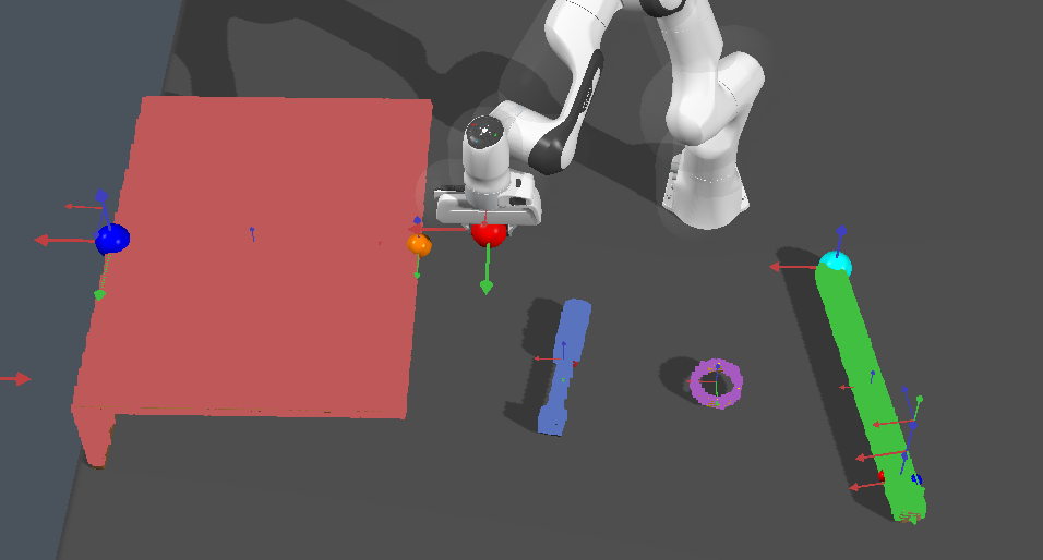
VLM-generated semantic waypoints that later guide the KOMO trajectory optimization.
The VLM operates on RGB images and outputs pixel coordinates [u, v]. These are lifted to 3D world-frame keypoints using the depth channel via camera intrinsics.
The resulting camera-frame point is transformed to world coordinates using the camera extrinsics. The VLM-predicted functional contact pixel is back-projected this way and then snapped to the nearest point on the selected tool's point cloud, yielding the refined 3D contact keypoint c.
Beyond tool selection and keypoint prediction, GPT-5.5 serves as a semantic motion planning assistant — providing waypoints that guide the KOMO trajectory optimizer for each scenario.
The VLM is queried for approach angles, target positions, and directional vectors. These serve as semantic waypoints that constrain the KOMO optimizer's trajectory phases.
The VLM is queried multiple times to identify the functional tool tip or contact point from annotated views and cluster context. This is especially useful for selecting the distal end opposite the grasp region instead of treating the grasp side as the contact tip.
For constrained spaces, the VLM identifies key geometric points (A, B for sweep direction; G, C for tool axis) that drive vector-based tool orientation alignment.
VLM analyzes cluster positions, object identities, and spatial relationships to reason about which side to approach from and how far objects must be moved to become reachable.
To counter spatial myopia, the JSON schema mandates three explicit reasoning steps before any coordinate regression is allowed:
step1_geometry_analysisDescribe the physical shape of the selected tool and locate its extreme boundaries in the image.
step2_grasp_locationIdentify the exact region designated for robotic contact — e.g., "the right-most end of the stick".
step3_contact_tip_locationUsing the grasp location as anchor, deduce the exact opposite functional extremity. Only then is the pixel coordinate [u, v] requested.
This figure illustrates how the Chain-of-Thought prompt guides the model to find the functional contact point C in the shelf scenario by first identifying tool extremities, then anchoring the grasp, and finally selecting the distal pushing tip.
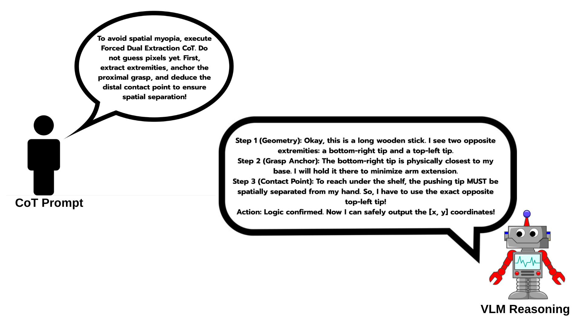
CoT.pngIllustrative example of the reasoning process used to avoid spatial myopia when predicting the functional contact point for the shelf task.
Single instruction: select a tool and output pixel coordinates. No schema, no task context.
Defined JSON schema with named fields for tool, grasp region, pixel coordinates, and confidence. No scenario context.
P1 plus full scene context and, where applicable, calibrated handle coordinate hints from gt.json.
P2 plus explicit anti-failure constraints such as "do not grasp the functional tip" and self-check reasoning fields.
Three constrained tabletop manipulation tasks. Each scenario details the specific role GPT-5.5 plays in guiding motion planning beyond mere tool selection.
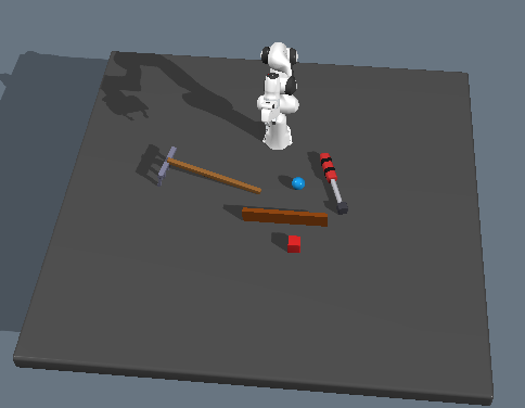
scenario1_wall_retrieval.pngTarget object behind a rigid wall, retrieved by grasping one end of a rigid tool and dragging.
PULL
scenario2_screwdriver_insertion.pngRotational actuation of a target using a screwdriver-like tool with a VLM-determined rotation waypoint.
INSERT / ROTATE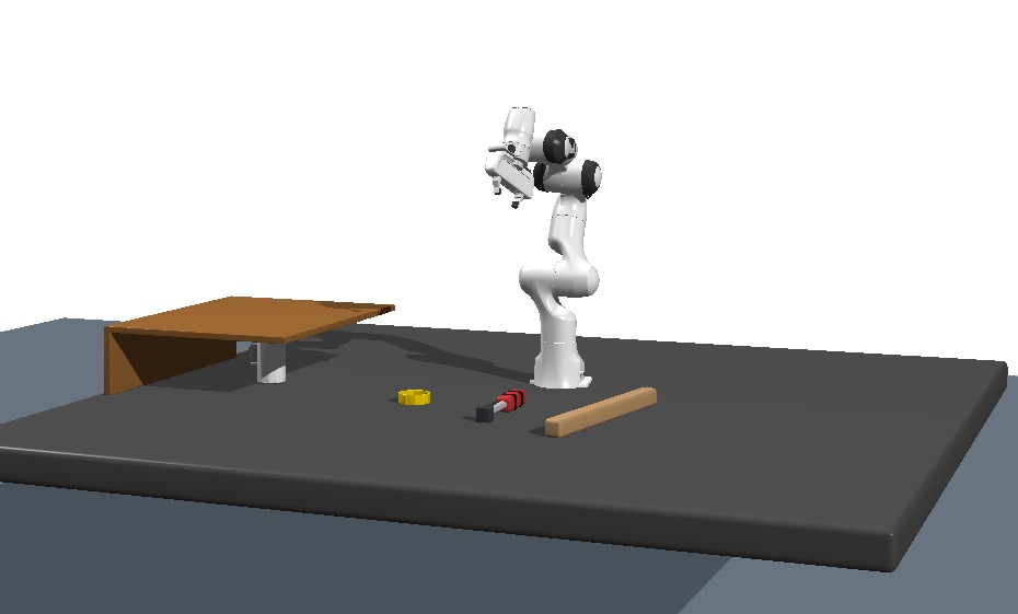
scenario3_shelf_retrieval.pngCup under a low-clearance shelf swept out with vector-aligned tool orientation and brought into the robot's reachable workspace.
SWEEP → GRASPA target object is placed behind a rigid wall, beyond the robot's direct reach. The system selects a long, rigid tool, grasps it from one end, and uses the opposite tip to drag the object into the reachable workspace. The primary geometric challenge is accurate functional tip localization: the contact point must be at the far end of the tool, not its center.
During the motion planning stage, the VLM semantically understands the environment and performs semantic planning over the detected clusters. It is queried to determine the approach angle and the direction in which the functional tip should be oriented — acting as a waypoint generator. The functional tip is then aligned toward this VLM-defined point. Afterwards, the VLM is queried a second time to determine how far the target must be dragged so that it becomes reachable by the robot, providing a drag endpoint waypoint that terminates the pull motion.
A target object requires actuation via a rotational motion. The VLM selects a screwdriver-like tool from the segmented point cloud clusters, and the best antipodal grasp point is computed within the VLM-specified handle region.
The VLM analyzes the scene and determines an appropriate rotation waypoint for the screwing motion. This waypoint is also used to align the tool along the vertical axis before the screw motion begins. Once the functional tip (back-projected to 3D from the VLM's contact pixel via the depth channel) reaches the target position, the KOMO planner executes the rotational trajectory. The VLM thus guides a non-translational end-effector motion entirely through semantic scene reasoning.
A cup placed under a low-clearance shelf cannot initially be reached by the robot. The robot must navigate a pushing tool through the narrow gap and sweep the cup into a position within the robot's reachable workspace. This is the most geometrically constrained scenario: incorrect tool orientation causes shelf collisions or joint-limit violations.
The VLM is queried in a Chain-of-Thought manner to identify the functional tip (C) and grasp point (G), constructing the tool axis vector GC. It also determines two points A and B behind the shelf edges — one near the robot side, one at the far side — defining the sweep direction vector AB. The tool orientation is then adjusted until AB ⊥ GC (computed via dot product), preventing shelf collisions. The robot sweeps with the tool guided by the VLM-defined point A and height. After sweeping, the cup is brought into a position within the robot's reachable workspace. This multi-query VLM strategy makes the pipeline robust to domain randomization and varying initial tool placements.
Each scenario ablation is run as 3 scene variants × 4 prompts × 5 repeats = 60 VLM calls. We evaluate prompt detail, visual cluster grounding, and model size. Annotated mode uses DBSCAN-derived labels and bounding boxes, while raw mode removes these anchors. Metrics follow the final report: Tool = correct tool selection, Hit = 2D grasp hit rate, AFR = antipodal feasibility rate, and Dev. = grasp deviation.
Wall retrieval strongly benefits from explicit anti-failure guidance. P3 gives the highest hit rate and the lowest deviation in every reported setting.
| Model | Mode | Prompt | Tool | Hit | AFR | Dev. |
|---|---|---|---|---|---|---|
| 4o | Ann. | P0 | 0.57 | 0.00 | 0.07 | 210.2 mm |
| 4o | Ann. | P1 | 0.67 | 0.00 | 0.08 | 231.5 mm |
| 4o | Ann. | P2 | 0.73 | 0.13 | 0.20 | 160.6 mm |
| 4o | Ann. | P3 ★ | 0.93 | 0.87 | 0.87 | 32.8 mm |
| 4o | Raw | P0 | 0.73 | 0.00 | 0.00 | 220.4 mm |
| 4o | Raw | P1 | 0.72 | 0.29 | 0.29 | 220.3 mm |
| 4o | Raw | P2 | 0.87 | 0.00 | 0.00 | 245.7 mm |
| 4o | Raw | P3 ★ | 1.00 | 1.00 | 0.93 | 17.6 mm |
| 4o-mini | Ann. | P0 | 0.90 | 0.20 | 0.07 | 119.1 mm |
| 4o-mini | Ann. | P1 | 0.70 | 0.20 | 0.00 | 131.9 mm |
| 4o-mini | Ann. | P2 | 0.77 | 0.07 | 0.07 | 185.2 mm |
| 4o-mini | Ann. | P3 ★ | 0.95 | 0.73 | 0.33 | 7.1 mm |
Screwdriver insertion improves progressively from P0 to P3. Minimal prompts can produce very large deviations, while P2/P3 substantially stabilize spatial localization.
| Model | Mode | Prompt | Tool | Hit | AFR | Dev. |
|---|---|---|---|---|---|---|
| 4o | Ann. | P0 | 0.70 | 0.10 | 0.20 | 47969.0 mm |
| 4o | Ann. | P1 | 0.67 | 0.10 | 0.65 | 71.2 mm |
| 4o | Ann. | P2 | 0.80 | 0.67 | 0.65 | 1.1 mm |
| 4o | Ann. | P3 ★ | 0.80 | 0.83 | 0.65 | 0.2 mm |
| 4o | Raw | P0 | 0.52 | 0.03 | 0.13 | 27037.0 mm |
| 4o | Raw | P1 | 0.50 | 0.15 | 0.20 | 215.7 mm |
| 4o | Raw | P2 | 0.70 | 0.46 | 0.37 | 37.4 mm |
| 4o | Raw | P3 ★ | 0.71 | 0.60 | 0.49 | 4.5 mm |
| 4o-mini | Raw | P0 | 0.06 | 0.04 | 0.20 | 3252.4 mm |
| 4o-mini | Raw | P1 | 0.56 | 0.30 | 0.37 | 48.7 mm |
| 4o-mini | Raw | P2 | 0.82 | 0.54 | 0.68 | 16.1 mm |
| 4o-mini | Raw | P3 ★ | 0.74 | 0.72 | 0.69 | 8.0 mm |
| 4o-mini | Ann. | P0 | 0.72 | 0.17 | 0.43 | 1652.0 mm |
| 4o-mini | Ann. | P1 | 0.69 | 0.32 | 0.49 | 38.3 mm |
| 4o-mini | Ann. | P2 | 0.74 | 0.67 | 0.56 | 8.5 mm |
| 4o-mini | Ann. | P3 ★ | 0.81 | 0.83 | 0.77 | 0.7 mm |
Shelf retrieval is the hardest setting because the model must identify both the correct tool region and the functional end for sweeping. P3 improves tool selection and reduces deviation across all reported shelf settings.
| Model | Mode | Prompt | Tool | Hit | AFR | Dev. |
|---|---|---|---|---|---|---|
| 4o | Ann. | P0 | 0.42 | 0.25 | 0.07 | 136.7 mm |
| 4o | Ann. | P1 | 0.65 | 0.30 | 0.05 | 147.7 mm |
| 4o | Ann. | P2 | 0.70 | 0.05 | 0.07 | 186.5 mm |
| 4o | Ann. | P3 ★ | 0.90 | 0.65 | 0.07 | 56.1 mm |
| 4o | Raw | P0 | 0.62 | 0.15 | 0.04 | 112.1 mm |
| 4o | Raw | P1 | 0.70 | 0.20 | 0.02 | 132.1 mm |
| 4o | Raw | P2 | 0.70 | 0.05 | 0.07 | 186.5 mm |
| 4o | Raw | P3 ★ | 0.90 | 0.55 | 0.06 | 56.1 mm |
| 4o-mini | Ann. | P0 | 0.78 | 0.20 | 0.05 | 125.1 mm |
| 4o-mini | Ann. | P1 | 0.76 | 0.30 | 0.00 | 149.1 mm |
| 4o-mini | Ann. | P2 | 0.79 | 0.07 | 0.07 | 191.5 mm |
| 4o-mini | Ann. | P3 ★ | 0.90 | 0.55 | 0.27 | 28.1 mm |
Structured CoT has the strongest impact in the shelf scenario, where success improves from 3/10 to 6/10. The improvement comes mainly from fewer functional contact-point failures.
| Scenario | With CoT | Without CoT |
|---|---|---|
| Wall retrieval | 8 / 10 | 7 / 10 |
| Screwdriver insertion | 7 / 10 | 7 / 10 |
| Shelf retrieval | 6 / 10 | 3 / 10 |
In the shelf scenario, 6 out of 10 rollouts are successful. Among the 4 failures, 2 are caused by selecting the wrong A–B shelf-edge pair, while the other 2 occur because the predicted C point is placed on the same tool end as the grasp instead of the opposite functional tip.
Before adding Chain-of-Thought reasoning, only 3 out of 10 shelf rollouts were successful. The main failure mode was spatial myopia: C was often predicted near the grasp region instead of the distal contact tip. In those failures, 2 came from the wrong A–B edge pair and 5 came from incorrect C-point selection.
| With CoT | Without CoT | |
|---|---|---|
| Successful rollouts | 6 / 10 | 3 / 10 |
| Failure breakdown | ||
| Wrong A–B edge pair | 2 | 2 |
| C placed at same end as grasp | 2 | 5 |
| Total failures | 4 | 7 |
Failure case where the VLM predicts an incorrect waypoint for screwdriver insertion, causing the tool tip to approach the target with the wrong spatial alignment.
Failure case where the VLM selects an unsuitable tool for the wall-retrieval task, preventing the robot from correctly pulling the target object into the reachable workspace.
The main shelf gain comes from reducing C-placement failures from 5 to 2; the A–B edge-pair error stays at 2 failures in both settings.
DBSCAN-derived labels and cluster summaries anchor the VLM to candidate tool regions, converting raw coordinate regression into selection-then-localization.
The shelf task requires relational geometry over A, B, grasp G, and functional contact C, making it more sensitive to spatial myopia than wall or screwdriver tasks.
Once the KOMO trajectory is generated, the system does not yet re-plan after unexpected slip or contact; closed-loop recovery is a natural next step.